It’s the time of year for saving money!
 In a previous article (“One down…”), I told you that I had discovered (from the response to my article just before that one) that even when I wasn’t writing about cables, cables were what people seemed to comment on and that, having learned my lesson, I would therefore do a series of articles on how cables work (not DO they work; everybody – even the trolls — knows my position on that issue already).
By way of introducing that subject, I said (in “One down…”) that, as far as the conventional Electrical Engineering position on cables went, there were really only four significant factors to be considered: Resistance (R), Inductance (L), Capacitance (C), and Characteristic Impedance (ZO), and I went on to say that “…there are a great number of other things that also affect cable performance and, even of just the four given (R, C, L, and ZO), two are, FOR MOST AUDIO APPLICATIONS, of lesser significance than the others and one may make absolutely no difference at all!”
 Those two “less significant” factors are, for the record, R and ZO, and of the two, the one that can be of no importance at all is ZO. In the article “One down…”, I tried, apparently with some success, judging by your comments, to show you that resistance is of little practical importance in audio cable design. Now, in this article, I’m going to attempt to do the same for Characteristic Impedance.
Before I go any further, though, let me define what I will mean when I refer to cables for “audio applications”. Those are interconnects and speaker cables of , at most, the maximum lengths likely to be encountered in a home audio or Home Theater system (typically just 1 to 3 meters long, and rarely, if ever, over 50 feet [=15.24 meters]), and they will have been designed to operate at frequencies which are either in, or are reasonable harmonics of, the normal audio range – that being, for purposes of this article, DC (= 0 Hz) to about 80 kHz (the fourth harmonic of 20kHz, which is the frequency generally accepted as the upper limit for normal human hearing). Because so much of the modern audio experience is, at least at one point, digital, I’ll also touch on digital and/or video cables, even though, because of the transfer rates or frequencies of digital or video signals, they should more rightly be considered RF than audio applications.
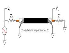
 If you really want to read about it, there’s a whole lot of information about characteristic impedance on the internet. For purposes of home audio, though, a thorough grounding in it really isn’t necessary. What IS necessary is to understand that Characteristic Impedance (from this point on, I’m just going to call it “ZO”) is about matching identical source and load impedances at the two ends of a signal path with a cable of the same ZO, and about what happens (stated as simply as possible, wherever possible), IF IT’S POSSIBLE TO DO but you DON’T do it. In the case of a perfect match, an AC signal of whatever frequency will be “transmitted” (hence the terms “Transmission lines” and “Transmission Line Theory”) perfectly along a transmission line as if that line were infinitely long: Signal will just pass through as if it could keep on going forever and it will never “bounce” back. When the impedance match of all three elements (source, load, and cable) ISN’T perfect, though, BUT OUGHT TO BE, the signal acts as if the transmission line has an end to it and, hitting that “end”, the signal (or at least a part of it) is reflected back toward its source, and can produce cancellations or standing waves or both, which can appear as black lines, “dropouts” or their equivalent on video or digital signals, or as high frequency losses or garbling if in the audio range.
For most audio applications, impedance matching – ZO — isn’t an issue, for the simple reason that THERE’S NOTHING THERE TO MATCH!
]]> “Unbalanced” components and interconnects (sometimes called “single-ended”) typically use RCA connectors and typically have a cable connecting a low-impedance (typically 50 to 250 Ohm) source output to a high impedance (typically 10,000 to 47,000 Ohm) “loading” input. That being the case, which impedance should the interconnecting cable try to match? Obviously, it can’t match both, and there’s really no point in matching either one, because the high impedance loading of the circuit makes it possible to effectively transmit the signal without losses even with no matching at all.
“Balanced” components (which may or may not be fully “differential” in operation) are typically interconnected with XLR connectors and, for home audio operation, are normally at least “nominally” impedance-matched using a “nominally” impedance-matched cable. The problem is that word “nominally”. Although, in the old days of radio (and, even earlier, the telephone company), the standard impedance to match was 600 Ohms (which was the [approximate] “natural” ZO of a long twisted pair of 16 gauge wires), in more modern times, nominal impedances of anywhere from 50 to 250 Ohms have become the norm and, because of differing manufacturer-to-manufacturer input and output impedance standards, even a nominally impedance-matched circuit may not be ACTUALLY impedance-matched.
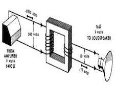
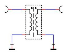 Speaker cables are another application where impedance matching is not possible. Even though some cable manufacturers will occasionally try to pitch “genuine 4 Ohm” or “genuine 8 Ohm” speaker cables, there’s really nothing there to match. “Aha,” you say, “that’s not true! I CAN match the 8ohm output tap on the output transformer of my vacuum-tube amplifier to my 8 Ohm speakers, so shouldn’t I, therefore, use a speaker cable with a characteristic impedance of 8 Ohms?”. The answer is “No.” In the first place, although it’s possible that that 8 Ohm tap really has an 8 Ohm output impedance, It’s more likely that that claimed “8 Ohms” is a “nominal”, rather than actual impedance, and was chosen by the amp’s manufacturer NOT to match, but to work well with 8 Ohm speakers. And even your speakers, themselves, (unless they’re a near purely-resistive load, like Magnepans and some other “planar” designs), are only “nominally” 8 Ohm, and may have actual impedances, varying with frequency, of anything from a fraction of 1 Ohm to 40 or 50 Ohms, or even more at their low frequency resonance point. Finally (for speaker cables), if your amp is solid-state, instead of tubes, it doesn’t HAVE an output transformer, and its output to your speakers, instead of being anything like 8 Ohms, will certainly have an output impedance well under 8 Ohms, and possibly even as little as .001 Ohm. There’s no impedance match there, OR at the speakers.
About the only things in home audio that DO allow for impedance matching and thus make ZO an important consideration aren’t even really audio applications at all: they’re the digital and video cables we use with our digital storage or playback systems. For them, because of the very high frequencies or transfer rates of the signals they carry, 75 Ohms (or 110 Ohms, for AES/EBU digital) is a fairly rigid standard, although +/- 5% is still considered “spot-on” for most applications and +/- 10% is acceptable for many. Even with these, though, and even despite the “perfect transmission line” claims made for systems with properly matched characteristic impedances all the way through, the real-life experience of High-End and custom installers all over the world has shown that, especially for HDMI, the length of the cable can be at least as important as its characteristic impedance, and possibly even more so.
Two down…
