
It’s the time of year for saving money!
Hurray! Either because I can’t think of anything else to say about RCA connectors; because, like the Masters of the ancient Guilds of yore, I’ve gotten secretive and unwilling to share my knowledge with the public; or because I’m simply running out of titles inspired by 1930s cliff-hanger serial movies; I’m finished with RCA connectors and ready to move on to something even weirder – XLR connectors, the near absolute standard for balanced lines, recording and most professional audio applications.
 The XLR connector (earlier sometimes known as the “Cannon plug”), was invented by Cannon Electric Co. of Los Angeles primarily for military applications and as a replacement for the similar, but not compatible DIN connector. Originally, it was a simple “push-together” arrangement (the Cannon “X” connector), but after 1950, a locking mechanism was added for greater contact security and it became the Cannon XL (“L” for locking). Finally, after 1955, synthetic rubber insulation was added to the female versions, and it became the “XLR” connector, and was available with anything from 2 (now obsolete) to 7 pins. [http://en.wikipedia.org/wiki/XLR_connector]
The connectors were a great commercial success across a broad range of applications and were copied, modified, and/or improved by a number of companies, including Amphenol, Switchcraft, Neutrik, and others, and in 1963, Cannon Electric was acquired by and became a division of ITT.
For audio applications, the version that became the standard for professional use had three pins: one for ground, and two for signal. This is perfect for balanced line operation.
 In the more common “unbalanced” or “single-ended” operation – circuits that, at line level, typically take RCA connectors — there are only two wires or contacts (the right word might be “leads”, “terminals”, or “pins”, but, for convenience, let’s just call them “leads” here) – the powered “hot” or “positive” lead (which can actually be either positive or negative, depending on the signal), and the “ground” lead, which always acts to complete the circuit for the other lead, regardless of that other lead’s polarity.
In a balanced circuit, on the other hand, there is no true ground and the two signal leads are both powered and of opposite and constantly changing polarity. It’s because of this that the two output terminals on a balanced-output amplifier, for example, (or the output leads on any other balanced circuit) are not referred to as “positive” and “negative” or “hot” and “ground”, but as “hot” and “cold”, and each one acts as ground for the other.
To understand how this happens, remember that a music signal is an alternating current, constantly switching in polarity from positive to negative and back again in accordance with the music. Remember, also, that current always flows from “positive” (a surplus of electrons) to “negative” (a temporary shortage of them). With that in mind, it’s easy to understand that, in a balanced circuit carrying a music signal, when the “hot” lead is positive, the “cold” lead will be negative, and vice versa, and that, as long as the circuit is complete, which one of the two leads is serving as “ground” for the other will constantly change.
There are all kinds of advantages to this mode of operation: For one thing, the simple fact that both “legs” of the circuit are powered means that the signal will have twice as much voltage and twice as much available current at any level, with, therefore, 6dB greater total signal strength and a resulting 6dB greater signal-to-noise (S/N) ratio. Another noise ratio improvement comes from a balanced circuit’s inherent characteristic of common mode rejection. Put most simply, when an external noise source – EMI or RFI interference – is present, it induces identical-but-out-of-phase noise in both of the circuit’s two legs and the circuitry simply cancels it out! From a cable standpoint (a subject you may by now know, is of special interest to me) it means that shielding of any kind, except in the highest electronic noise environments, may not be necessary, and that with shielding, (as provided for by the XLR’s third – actually #1 – pin) even the tiniest signal can be passed with full protection from environmental noise. The proof of this is that XLR connectors are the standard fitment for virtually all low impedance professional dynamic microphones even though those mic’s typically operate at a very low output level, in the range of only about -55 dB to -60dB (Ref: 1 mw / 10 dynes/ cm2). [http://www.coutant.org/666r/]
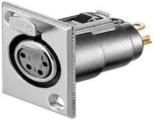 Unlike RCA connectors, where males are typically used at both ends of a cable and females are practically always chassis-mounted, XLR connectors are normally applied to cables with a female (3 holes) at the input end and a male (3 pins) at the output end of the cable. This same directionality of current-flow applies to chassis mount connectors for the electronics to which the XLRs connect: Females for inputs and males for outputs. For microphones, a male XLR is typically built into the body of the mic.
The directionality of connection that XLRs provide is great for pro audio applications and for stagehands and such, who regularly have to deal with great bunches of cables and who need to be able when hooking things up to tell which end of a cable is which just by looking at it – especially when they all look alike. But, while it can be a benefit in one way, it can also be a problem in another: Many high-end audiophiles believe that cables – the actual cable material, itself – are directional, and will sound better when run in one direction than another. With RCA connectors, that’s easily dealt with: Because the connectors are the same at both ends of the cable, all you have to do is to hook them up and listen, and then turn the cables around and listen again, choosing, if you hear a difference, the way you like best. To do the same thing with XLRs requires either two different sets of cables, terminated in opposite directions, or one set that you listen to, unplug, re-terminate in the opposite direction, and then listen to again. At best, that’s more work; and it may even be that, with all the time lost re-terminating that one set of cables, by the time you get it done, you will have forgotten which way sounded better, and the whole exercise will have been wasted. Oh, well…
There are a great many more strange and wonderful things to be said about XLR connectors. Assuming that I can keep coming-up with appropriate names for these articles, I’ll tell you more of them next time and in the installments following.
See you then!


