It’s the time of year for saving money!
Last, time, in Part 5 of this continuing series about phonograph records and the equipment for playing them, I did a brief recap of how and why both the LP record and the magnetic cartridge for playing it came about, and said that much of what they brought about – better sound, longer record life, and all the rest – may just have been unintended benefits of an effort to deliver longer playing time.
Those things were certainly for the better, but there were other consequences, too, that were more problematic than beneficial.
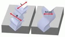
 As I said last time, any phono cartridge makes its output as a result of movement: Following the modulations of the recorded groove causes the stylus to move (side-to-side, for monaural, and at 45°, both side-to-side and up-and-down, for stereo), and, the more it moves, the more output there will be, regardless of type of cartridge. Going from 78rpm records to the new “LPs” (for “Long Playing”), meant that, in order to achieve its goal of 30 minutes of music per record side, the recording industry had, among other things, to move the groove sections closer together. That meant, in addition to just making the groove narrower (less distance from wall to wall), they also had to limit the maximum amount of groove modulation (groove “swing”) allowable, which limited the amount of movement-energy available to create cartridge output. The narrower, closer-together groove also required a smaller stylus to track it, which resulted in greater effective tracking force; which required a lowered tracking weight; which required higher cartridge compliance in order to still be able to track properly; which meant, at least until a whole new generation of ceramic cartridges came along, that magnetic cartridges were the way to go. They, plus the new, quieter and more durable vinyl records, gave better sound and longer record and stylus life, but the fact remained that magnetic cartridges still had far less output per unit of groove swing than their earlier crystal and ceramic predecessors, and that, coupled with limited-swing recordings could – even with the additional electronics required for pre-amplifying and equalizing them – make for unacceptably low output.
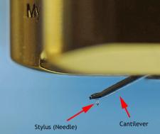
One way in which cartridge designers sought to increase output (in addition to seeking improvement to the actual moving magnet, moving coil, or moving iron “generator” mechanism) was to simply mount the stylus to a “cantilever” designed as a “Class 1 lever“. This is one that has its force (effort) at one end; its load at the other; and a pivot point (fulcrum) somewhere in between, and acts, depending on the specific positioning of the fulcrum, as a simple balance beam, or either to trade (if the fulcrum is closer to the load) increased force for reduced motion or (if the fulcrum is closer to the force) increased motion for reduced force. With, in the case of a phono cartridge, the “force” (the groove motion) at the stylus end and the “Load” (the generator) at the other end of the cantilever, setting the fulcrum closer to the stylus results in increased motion at the generator end and can make for higher output.
 This is mostly a great solution, but it does have its weak points: For one thing, having a Class 1 lever requires a fulcrum, and that, just in itself can pose a problem: Levers require the possibility of motion in order to operate. For monophonic (Monaural) recordings, the only motion to be accommodated is purely in the horizontal plane (side-to-side) and a fulcrum (the pivot for the cantilever) could be made of a “hard” material which would allow for very tight control of both its dimensions and the kind and direction of movement it allowed. That was important because (other than what resulted from the mechanical advantage created by the positioning of the fulcrum relative to the stylus and generator ends of the cantilever) any difference between the movement of the stylus in the groove and the movement of the generator-end of the cantilever will result in changes to the output of the cartridge and affect what we hear. Another factor was that excess clearance in the pivot could result in “chatter” – an actual banging of the cantilever against its pivot – which could not only affect the sound as just described, but could, if sufficient, actually create a sound of its own to add to the music.
With stereo recordings, the motional requirement of the pivot – and thus its potential for problems — is increased hugely: The pivot must allow for movement that is simultaneously side-to-side, up-and-down, and, because of the 45°/45° cutting angles of the groove, everything in-between. To make a “hard” pivot do that would require something like a captive ball, which would be analogous in function to a universal joint and potentially much more expensive to produce and to hold to tolerance than just a single-plane pivot. It could also be even more prone to “chatter” and the problems that can bring. Both “hard” and flexible pivots (pivots made of a flexible rubber or plastic material) are possible. Both can be, and have been made, and each has its own comparative strengths and weaknesses.
It’s not just the pivots, though, that can pose problems; the cantilever, itself, can be a significant source of inaccuracy, distortion, and “noise”.
 Obviously the cantilever, in order to provide mounts both for the stylus and for a magnet, a bit of iron or a pair of coils, and still make for increased motion at its generator-end for higher cartridge output, must have some length to it, and that’s part of the problem: Remember that the cantilever is a lever, and that the longer any lever is, the more likely it will be to bend when force is applied to it. Remember, also, that in a phono cartridge any bending will affect the sound (and, to some degree, even the output). For that reason, cartridge designers will always either try to make the cantilever in their designs either as short as possible; of as rigid a design and material as possible; or both. Dynavector – with its very-short-cantilever designs featuring square cross-section cantilevers made of actual ultra-rigid diamond – comes to mind here.
Diamond is probably the most exotic cantilever material to be used, but it’s certainly not the only one: Boron, another material known for extreme rigidity (as well as light weight) has also been used, and so have sapphire and even ruby, all in the quest for the most rigid – read that as “the most accurate” – cantilever possible. Other techniques, popular for lower-priced cartridges but also applied up into the higher (and even vastly higher) price ranges, include increasing the diameter of the cantilever for added stiffness and simply making the cantilever tubular, rather than solid. Both of these, either separately or in combination have been used with considerable success, even with cantilevers of a material as soft and relatively flexible as aluminum.
 Whatever the cantilever material or construction, and no matter how rigid its designers may succeed in making it, another issue that must always be dealt with whenever a cantilever is used is resonance.
That’s something of genuinely major importance, in more than just a single area of cartridge design. Unfortunately, I’m out of space for now, so let’s get into it next time.
See you then!