It’s the time of year for saving money!
I opened Part 1 of this series about Hi-Fi testing by asking what you would think of including durometer (hardness) testing as part of the information provided about the enclosure for a new speaker. Or of reviewing a new amplifier based on its weight. Or an audio cable based on how waterproof it is. All of those tests could be justified for those products, and would even, under the right circumstances, provide usable information that could help someone to make a buying decision.
 The real question, though, is not “can it be usable” but – assuming that not all information of every kind can be provided – is it the most usable information that can be provided within the available limitations?
Among the things I wrote about last time was frequency response — probably the most commonly provided item of information for most audio gear. Just about every manufacturer who releases any kind of test information or specifications at all provides a frequency response range for his products (20 Hz to 20 kHz, for example), with or without an accompanying range of variation (+/- 3dB, for example). Does it really mean anything, though? Is it really usable?
To show just how little a frequency response spec can mean, I gave one example where , yeah, sure it will do 20 Hz, but (because no limit of variation was stated, and 20 Hz was 40dB down from the 1k level) you’ll never hear it. I also gave three different examples of performance that would all fall precisely within the stated (+/- 3dB) limits but would all sound wildly different.
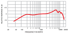 if you really want to have some advance clue as to what a thing is likely to sound like, what you need is a graphically plotted frequency response curve, but even those can be of little value: All anybody has to do to make a frequency response curve misleading is to either make its vertical (dB) scale sufficiently broad or to “tailor” its range so that it only shows the part of the overall response that will look good to a potential buyer. If you’ve ever bought a High-End phono cartridge, you may know what I mean: Most of those seem to come with a long skinny piece of paper folded-up in their packaging that shows the cartridge to have what looks like ruler-flat frequency response. In fact, that’s not true, but all they had to do to “improve” it was to make the dB increments on the narrow strip of paper their “curve” comes on (perhaps 2″ [5cm] tall by 8 1/2 ” [21.6cm] wide) so big (+/- 10dB or more per division) that even a couple of dB variance at any point looks tiny, and, if it’s a moving coil cartridge, and has a peak of even as much as 12dB at 30kHz or thereabouts, all they need to do to get rid of it is to limit the displayed range to something (20kHz, for example) below that, where the peak won’t show up.
Distortion is another test result that can be absolutely true but, for one reason or another, of little value: Back in the 1950s, when I first got started in Hi-Fi, it was normal to provide two different distortion measurements: “harmonic distortion” (“HD” or THD”– “total harmonic distortion”, as the term is used today) and “intermodulation” (“IM”) distortion.
What harmonic distortion refers to is spurious (not there on the original signal) sound that’s added to the musical or other signal by the equipment in the process of amplifying, transmitting, or transducing it. On a musical instrument, harmonics (additive frequencies at multiples of the fundamental resonance of a vibrating object [string, reed, column of air, etc.]) are supposed to be there; are generally regarded as pleasing; and their generation is one of the instrument’s major and characteristic functions. In a Hi-Fi sound system, though, it’s mostly a “no-no”.
 I say “mostly” because, while “even order” harmonic distortion (second, fourth, sixth, etc.) – the kind that tube electronics make the most of (as opposed to the “odd order” harmonic distortion that solid-state electronics tend to produce in equal quantity with the “even order” kind) is regarded by many people to be pleasant sounding, and to add to the “musicality” of the resultant sound. This may be the reason for the positive response many people have for “classic” tube sound, but the fact is that distortion, whether pleasing or not, is still distortion.
Besides just the electronics, harmonic distortion can also be produced by speakers, too — particularly where the frequency to be reproduced and the resonant frequency of the speaker system are close, (as in woofers and sub-woofers) and can result in a phenomenon called “doubling” where the stimulation of the woofer at its fundamental resonance frequency by the driving signal produces an effective second signal (stimulated harmonic distortion) at twice the frequency and at a volume similar to the frequency that’s supposed to be played. (for example, a 20Hz input signal could produce a 40Hz second tone of comparable volume) That’s one reason why sub-woofers, for example, have been known to show harmonic distortion figures as high as 40% or even more. (!)
Intermodulation distortion used to be one of the standard things to be measured on amplifiers and similar products, whether tubed or solid state. Unlike a simple harmonic, produced as multiples of a single fundamental frequency, the product of IM is a third frequency (similar to a “beat frequency” or “heterodyne”) produced by the interaction of two or more separate frequencies with non-linearities in the processing electronics, and can be either additive or subtractive and create its own chain of harmonics and sub-harmonics along the way. Because the most significant difference between harmonic and intermodulation distortion is the fact that harmonic distortion is produced by a single frequency and intermodulation distortion is caused by two frequencies or more (a music or similar signal), the practice of calling out a separate figure for IM eventually faded away and only a single figure – Total Harmonic Distortion (“THD”) which lumped both kinds of distortion together became the one normally given.
Another kind of intermodulation distortion – “Transient Intermodulation Distortion” (“TIM”)- came along, however, described by such notables as Matti Otala (designer of, among other things, the still much-to-be-desired “Citation” series of electronics from Harman-Kardon), Eero Leinonen, and John Curl (designer of some of the best electronics of all time, including his own “Vendetta” and “Blowtorch” preamps and many of the best products from Mark Levinson, Parasound, and others) This was seen as providing important insights into the mysteries of audio reproduction. I’m out of space, though, so let’s leave it and some other kinds of distortion for Part 3 of this series.
Stay tuned…