It’s the time of year for saving money!
There’s an old joke about a concert that doesn’t start on time and has the audience getting progressively and ever-more-vociferously restless until, finally – after however long — a man in a tuxedo (probably the impresario) comes out on stage and announces that the performance has been canceled and that all ticket money will be refunded because the scheduled soloist has, unexpectedly and unfortunately died. No sooner has he finished his announcement when someone up in one of the far galleries stands-up; yells out “Give him an enema!” and sits back down. The (probably) impresario is frankly taken aback by this, and says to the apparent heckler “But he’s dead”: to which the other man again yells out “Give him an enema!” Now completely flustered, the impresario, takes a handkerchief out of his pocket, wipes his forehead, and asks: “But he’s dead; what good can it do?” whereupon the other guy yells out “So? Can it hurt?”
 As a former (but still interested) cable designer, let me tell you that, IMHO, the bulk of the so-called “High-End” cables out there seem to have been designed by someone just like that guy up in the peanut gallery: With no true understanding of how things actually work, their “designers” just seem to have thrown together everything they’ve ever read in somebody else’s “White Paper”; seen in a high school physics text; or picked-up on the internet or in audiophile conversation, and combined it on the assumption that it’s all good, and it can’t possibly hurt – just like that suggested enema. Whether it actually works, though, or is just speculation or wish-fulfilling fantasy seems to be beyond either their ability or desire to determine.
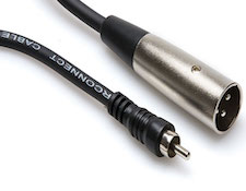
One of the things that sounds technical and that finds a willing audience among both the manufacturers and buyers of cables is the need to very precisely impedance match the connectors and the cables that they are fitted to. All kinds of commentary has been written on that subject, much of it pointing to the “need” to use impedance matching RCA connectors for digital or video applications.
In a previous article, I wrote about how the RCA connector had come about; that Its origins were for use as a “phono” connector at a time when the typical phono cartridge was crystal or ceramic with a multi-thousand-Ohm impedance; how – apparently out-of-the-air – people had later come to decide that it was actually a 50 Ohm connector, and that, because of that, it was unsuitable for 75 Ohm digital or video application. I also wrote, in that same article, about how a company called Canare was building RCA connectors that claim – at least when used with Canare’s own 75 Ohm cable – to be a true 75 Ohms. That’s all true, but how important is it? Does it really matter? Or is it just marketing or more amateur orthodoxy? You know what I’m talking about – like the amateur cook very precisely measuring the ingredients for a recipe he’s never made before, it’s the kind of obsessive attention to detail that people who have no solid background in what they’re doing use to give themselves comfort and to hide from others the fact that they don’t really know what they’re doing.
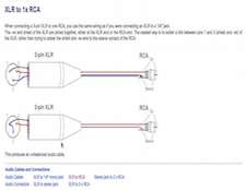 With RCA connectors, the fact that they have only two conductors makes it most likely that they will be used in (shielded or unshielded) unbalanced-line circuits, which probably, except for certain specialized applications like digital and video, will be “loaded” (usually with many times the output impedance of the source component) instead of impedance-matched. In fact, in most unbalanced circuits, impedance matching is simply not possible – the output impedance of the source and the input impedance of the load are wildly different, and there’s simply nothing there to match.
Circuits using XLR connectors are, however, something else, entirely. With XLR connectors (please remember that in these articles I’m always referring to only the three-pin version), the lines are (I’m going to add the “almosts” only to cover the unknown odd exception) almost always balanced and almost always impedance-matched, so one can reasonably guess that if connector-to-cable impedance matching is ever going to be important, it’s going to be here.
Even so, the range of applications for XLR-type connectors (including the Cannon “X”, and later the “XL” and the “XLR”) has been very broad: Their original application was for 600 Ohm signal transmission. Then, when they were applied to microphones as the standard low-impedance connector, the mics they were built into had impedances ranging all the way from 50 Ohms to 250 Ohms. It was the same thing for balanced line interconnects at all of the same impedances as the microphones. And, when the AES (Audio Engineering Society) and the EBU (European Broadcasting Union) got together to establish the “AES3” standard (in 1985, as revised in1992 and 2003), for transmitting two (stereo) channels of PCM audio between professional devices, the XLR was the connector they chose for 110 Ohm balanced line application (IEC 60958 Type I).
 With the AES, the EBU, and (later) the IEC (“The International Electrotechnical Commission”, known in French as the “Commission électrotechnique international”), all accepting it for S/PDIF application, it must be that the XLR connector either really has an impedance of 110 Ohms or that its actual impedance doesn’t matter. There really aren’t any other options. And, given that it has also been used and accepted by the professional audio institutional establishment at other impedances (600, 50, 150, and 250 Ohms) I can only take it as a tacit statement by that institutional establishment that impedance matching of cables and connectors, at least in applications that are of concern to audiophiles, is not a major concern.
Hmmmm… Could it be that cable-to-connector impedance matching is another one of those things that sounds like it ought to be a good idea and, where possible, “couldn’t hurt”, but that, like an enema for a dead man, shouldn’t be expected to do much at all?
There are all kinds of other weird, wonderful, and even outright silly things about cables and their connectors. I’ll write about some more of them next time
See you then.
