It’s the time of year for saving money!
In the last installment of this continuing series, I, in my most genteel form, started with a joke about an enema for a dead man, and went on to say that trying to impedance-match XLR connectors; the signals they carry; and the cables they’re connected to seems to be just about equally useful. This time around, I’m going to take a look at some other aspects of XLR cable design and talk a bit about how they can affect home and professional users.
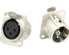 When I first designed XLR connectors for my old cable company, XLO Electric, my only concern was for High-End sonic performance. I didn’t really care about how others had approached the XLR design problem in the past, I just wanted my connectors to be the very best possible, NOW. Even so, my connectors still had to be compatible with other XLRs, in that they had to be able to plug into and carry signal to or from other brands or models, but other than that, I was pretty much on my own.
The first thing that I had to choose was the basic construction format that my XLRs would follow – how the parts of the connector would go together on assembly, to make the fully assembled cable termination — and, after taking a look at just about every other original style (meaning not a copy of somebody else’s product) on the market, I decided that a Neutrik-style assembly structure would be best for my needs.
That eliminates set screws and relies on a single screw-on “tail assembly” to hold everything in place, and I chose, for various reasons – not the least of which was the fact that it would allow me to use different permanent colors to identify the different stereo channels – to make the screw-on section out of a tough molded plastic material with silicon rubber strain reliefs for the cables. That was great for home use and for some of the less-rugged professional applications, but for television, for example, where miles of cable can be laying on the floor, getting constantly run-over by camera and mic booms and dollies, those plastic parts could have been risky and, despite all other considerations, the greater durability of metal ones might well have been preferred.
For use inside the connectors, as the combination cable clamp and internal securing device, I specified pieces made of Dupont™ Teflon™. This was chosen both for its limited flexibility and, as is always my preference with any non-conductive material that will be a part of my finished cables, for its low dielectric constant.
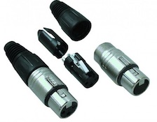 I also wanted to use Teflon™ for the molded plastic blocks holding the actual connecting parts — pins for the males and pin-clamps for the females. This would have been my preference, both for dielectric reasons and for soldered-on assembly: Teflon’s™ very high melting point of 620 degrees Fahrenheit would have meant that no amount of clumsiness with a soldering iron could have spoiled a connector, but the fact that it’s known for a high degree of mold-shrink could also have resulted in loose or “wobbly” pins or pin-clamps and compromised the quality standard that I wanted to maintain. Another problem with Teflon™, incidentally, is that it’s not “cross-linked” and has no “memory”, so it can eventually just flow away from its original shape and, in certain applications, create problems.
Using a “rubber” material, like other – usually “pro-sound” or military-oriented — XLR manufacturers do (The “R” in “XLR” is for rubber) had its own problems, so I contacted General Electric, a major specialty plastic supplier, for help and, after consulting with some of their project engineers, was allowed to buy a quantity of one of their, at the time, not-yet-commercially-released engineering plastics which offered all of the molding and dielectric characteristics that I wanted and was completely stable in holding its shape.
That left only the pins and pin-clamps to consider before I could have XLR connectors produced for me.
At the time, the pins of most generally available XLR males were made – like most connectors – out of “cartridge” or “free-cutting” brass rods, rounded at one end; with a scooped-out solder well at the other, and nickel-plated for a bright and durable finish. The female pin-clamps, too, were nickel-plated, but because of the need for springiness, were usually made of either steel or phosphor bronze. These materials and the nickel plating applied to them were inexpensive and offered relatively good electrical conductivity and the necessary high level of durability for “pro” applications. The brass was also relatively easy to machine.
For my use, though, terms like “relatively good” weren’t sufficient, so the pins for all of
XLO’s premium connectors (both RCA and XLR) were turned from Tellurium copper and drilled hollow, almost to the very end, to minimize in-circuit mass. The female pin-clamps were made from a special Brush-Wellman (now Materion) Beryllium Copper alloy, chosen both for its good spring quality and to avoid any residual magnetic effects. And, for the same reason, nickel plating was replaced with direct (no intervening metal substrate) gold. Nickel is one of the “Iron Triad” metals (Iron, Nickel, Cobalt), and, as such, will take and hold a magnetic charge – something that may be of little or no concern for many commercial, “pro”, or military applications, but is completely unacceptable for High End Audio.
Was the direct gold better? For High End audio, certainly, but High End connectors tend to be connected once and to just stay connected, with relatively few changes over time. In pro applications, connections may be made; unmade; and re-made as much as many times a day, and thin direct gold plating, such as I used just to prevent oxidation of the contacts, might very well have been – because it could quickly wear-off under such circumstances – unacceptable to the professional market.
You see? It really IS “different strokes for different folks”!
There are all kinds of other weird, wonderful, and sometimes even silly things about cables and their connectors. I’ll write about more of them next time
See you then.
