It’s the time of year for saving money!
In earlier parts of this series on speakers and bass, I told you that, even if the drivers used for bass reproduction make fabulous bass, if the pressure waves coming off the front and back sides of their diaphragms (which are necessarily out of phase with each other) meet and cancel-out, you’re not going to hear it. That means that, at the very least, if we want to hear the low frequency components of our music, we’re going to need some kind of a divider to keep those waves apart.
 The very simplest divider possible is nothing more than a very large board (an “infinite baffle”) with a hole in its center over which the bass driver is mounted so that the sound from its front comes out on one side of the board and the sound from its back comes out on the other. That will work just fine, as long as the board is big enough so that the distance in every direction from the outer edge of the driver to the edge of the board is more than half the wavelength of the lowest frequency we want to hear. Because half the wavelength of a 20Hz tone is about 28 feet (about 8 ½ meters), that means that if we want to hear really deep 20 Hz bass, we’re going to need a really big board (more than 56 feet plus the diameter of the driver across) and a really big house to put it in. Or, in the likely case that that’s not practical, we’re going to need another way to keep the waves from coming together and canceling.
Probably the easiest way to do that is just to trap the back wave in a closed box big enough that the pressure changes from the movement of the driver’s diaphragm won’t be able to slow or impede the diaphragm’s movement. That kind of box is also called an “infinite baffle” and it and any other way of separating or eliminating the back wave – including venting it to another room or to the outdoors, or just plain – as with a “transmission line” enclosure – absorbing it out of existence, will also do the job.
You don’t have to lose the back wave, though. There are also ways of using the back wave to augment the front wave to either make for louder or deeper bass or to make the same bass level on less amplifier power.
 One of these ways ― actually, several of them ― involve “bass reflex” speaker enclosures. As I told you last time, this kind of enclosure uses the principle of the Helmholtz Resonator to excite the air inside a ported box (one with a hole in it) to produce a new reversed-phase (to make it the same as the phase of the front wave) bass signal to reinforce the signal from the front of the driver, either giving deeper bass or more power (twice as much = 3dB more) to the sound pressure coming off the front of the driver.
In designing any bass reflex enclosure, the very first problem that must be addressed is how to “flip” the phase of the back wave (the sound coming off the back of the driver) so that it will be the same as the phase of the front wave and, when the two meet and add algebraically, they won’t cancel, but will reinforce each other. Interestingly, the way that’s accomplished is reminiscent (No, not the same as, but reminiscent) of the way an amplifier works: As I wrote in this publication back in 2013, amplifiers don’t amplify, what they do, instead, is to use a small signal (the input ) to “gate” a larger current flow (from the amplifier’s power supply) and turn it into a different, but larger and out-of-phase version of itself which is then either used as final output or goes on for further amplification. Where the two processes are similar is that both use one signal to control another and to reverse its phase and that it’s the new signal created by the input signal that becomes the output. Where they’re different is that in an amplifier, the created signal is a bigger replica of the smaller one and in a bass reflex enclosure the output signal may be at a different frequency or of a different frequency balance than – and therefore completely different from — the input signal.
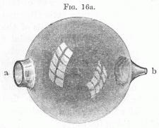
So, what really happens in a bass reflex enclosure? As the diaphragm of the driver moves back and forth a wave of pressure is generated off the front of the driver’s diaphragm and is radiated out into the surrounding air for us to hear. At the same time, another pressure wave – out of phase with the front one – comes off the back of the diaphragm to stimulate the column of air trapped inside the enclosure. As all things do when stimulated, that column of air vibrates at a level of energy determined by the “stimulating” energy applied to the diaphragm and at a frequency (its “fundamental resonance”) determined by the size of the box and the nature (shape, size, and length) of the port.). It’s fairly easy, these days, to calculate a resonance frequency that will be out of phase with the back wave that stimulates it (In phase, therefore, with the front wave) and that will, because it’s at a lower frequency than the fundamental resonance of the bass driver, serve to extend the bass response of the driver/enclosure system below that of the driver, itself.
 At least two major problems exist, though, with bass reflex systems; The first is that, in order to create it, the signal from the diaphragm must always come before the signal from the port. That means that the port output is always at least one full waveform (360°) late, dulling transient response and, because of hangover of the stimulated resonance, potentially “smearing” the bass. The other is a tendency toward “one-note” bass at the fundamental resonant frequency of the air in the enclosure.
This last, the tendency toward one-note bass, was particularly strong in the earliest days of bass-reflex enclosure design, when the output “port” was often nothing more than one or more holes cut or drilled in one face of the enclosure (In fact, before easy calculation was available, one technique for “tuning” a bass reflex enclosure was to simply start with a sealed box of the size ultimately intended, mount the driver in it, and measure the bass output. Then a small hole – usually ¼” or less – would be drilled in the box and the bass would be measured again. Then another hole would be drilled and the output would be measured again, and again, and again after each new hole, continuing to drill and measure as the bass got better and deeper each time until, with the drilling of the last hole, the bass either didn’t get any better or actually got worse. At that point, the last hole would be plugged with a simple wood screw and, if the speaker was a prototype or test unit being built for later series production, the holes would be counted; their total area would be calculated; and that total would become the port size to be drilled or cut into the enclosures for the production versions.)
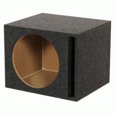
 Later bass reflex enclosures added a tube of whatever diameter (or other shape) and length to allow for the “tuning” of the port and to allow for the lessening of one note bass by actually having two different augmentative resonances – one produced by the air in the box and the other by the air in the port — to extend the bass response more smoothly over a broader range.
A bunch of other techniques to do that same thing were also tried – everything from “distributed” port designs, to “resistive” ports, to passive radiators, and more. I’ll tell you about some of them and how they worked (or didn’t work) next time.
See you then.