It’s the time of year for saving money!
Among other things, I wrote last time about some of the kinds of distortion inherent in our supposedly “high fidelity” audio systems – what they are, how they work, and how important a published test of them might be to an audiophile trying to make an informed buying decision. One of those distortion types was Intermodulation Distortion (“IM”), and after briefly describing it, I mentioned yet another type of distortion that has a similar-sounding name; that’s also worth knowing about; and that I said I would describe more fully in this present article:
 Transient Intermodulation Distortion, was brought to the attention of the Industry and the audiophile public by Matti Otala (best known in the United States for his cutting edge designs for the classic and still highly desirable “Citation” line of electronics from Harman-Kardon), researcher Eero Leinonen, and John Curl (whose initials, “JC” appear on some of the very best solid-state electronics ever produced, including designs for Mark Levinson, Parasound, and his own “Vendetta” and “Blowtorch” preamps). Those men said that a “… lack of correlation between conventional amplifier distortion measurements and listening tests has been noted by many designers of audio equipment” and, continuing that “Modern amplifiers often measuring under 0.01% total harmonic distortion at 1 kHz or below 0.1% intermodulation distortion, as measured with the SMPTE method, may sound completely unacceptable”, wrote a number of papers on TIM that were published by the Audio Engineering Society (AES); were referenced in other learned journals; and became a major source of inquiry and concern at the time. (the paper A Method for Measuring Transient Intermodulation Distortion (TIM) was presented at the 55th convention of the Audio Engineering Society in New York on October 30, 1976)
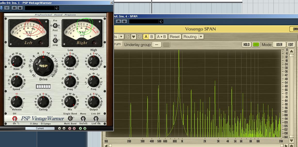
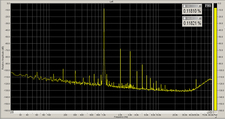
If you really want to understand TIM, I urge you to read those papers. For those of you who will be satisfied – at least for now – with just the basic idea of what TIM is and can then decide if you want to learn more, here’s an illustration that was run past John Curl, himself, in conversation just the other day and was accepted as being not too far from accurate: Imagine that you have a shotgun and that you fire it into the air and, although it’s only charged with a single kind of pellets, when they fall back to earth there are all kinds of other things mixed-in with them. Now let’s suppose that, instead of a shotgun blast fired into the air, what you fired off was a high frequency sine wave (typically 15 kHz with a peak-to-peak amplitude ratio of 4:1) backed by a bandwidth-limited square wave, and that you “fired it” into an “op-amp” – one of the functional sub-modules commonly used in amplifier and other electronic design. If when you measured the output or looked at it on a ‘scope, in addition to what you had put in, you found other bits of information at other frequencies (analogous to the other junk that fell down with your shotgun pellets), that extra information would be Transient Intermodulation distortion generated by the interaction of the signal frequencies and flaws or imperfections in the equipment and would typically be different in both amplitude and frequency from the more commonly measured “static” intermodulation distortion.
 So, that’s good and valuable information, right? And it should be included on every “spec” sheet for practically every component we might consider buying? Well, yes, but no. Whether because the discovery of TIM resulted in significant improvements in op-amps or in the things that use them, or if the knowledge of our industry’s engineers and designers has simply gotten to the point where they can deal with it; when I asked John Curl about why we no longer see TIM specs included with other information about our equipment as it had been in earlier times, his reply was that the testing could still be done, and that he will even do it himself, occasionally, but the fact of it is that op-amps and other similar devices that had, in times past, been plagued with TIM have gotten so good in recent years that practically anything now on the market will pass the TIM tests easily, and it’s simply no longer a consideration.
Another form of distortion that I’ve never seen a test spec for is “compression” distortion. I was reminded of this by a reader who responded to an earlier article in this series, and even though you may never have a problem with it, I think it’s still worth mentioning.
 To introduce it, let me just say that it’s similar to what happens in an ordinary fuse — you know, those things that we install as safety factors so that we don’t blow up our equipment or burn down our house: In a fuse, as in any conductor, the intended amounts of current will pass through it with little resistance (although we may sometimes feel a resistance-caused warming of the power cord or even the plug of a high-current device). As the current drawn increases beyond the designed-for range, though, higher current flow causes warming, which causes increased resistance, which causes more warming, and around and around, until the fuse blows, the device fails, or a fire starts and the house burns down.
That’s what happens with compression distortion before any of the more dire consequences: Excessive input causes resistance, which works to reduce effective output, with the result that the input curve and the output curve no longer match and we no longer hear what we ought to. This resistance can be either electrical, mechanical, or both – as happens commonly in speakers that are called upon to produce more than their planned output. For one thing, greater input will cause a speaker’s diaphragm to move greater distances forward and back. In accordance with Hooke’s Law, greater distance traveled will, in itself, result in greater spring tension produced by the driver’s spider and surround. This, added to the greater force needed (F=MV2) to stop the diaphragm and turn it back around to move in the opposite direction combine to produce greater mechanical resistance and reduced output per unit of input energy. As this is occurring, more and more current is fed into the driver’s voice coil to increase the output, and that results in a warming of the voice coil identical in kind and cause to the warming of a fuse or any other current-carrying wire. While all this is going on, there’s a clearly audible reduction in audible dynamics and, ultimately, the voice coil will get so hot that it will either burn itself out or melt the glue holding it to its former and kill the driver that way. This resistance-to heating -to-greater resistance-to burnout cycle can happen in both the speakers and the amplifiers driving them, and can be the bane of Sound Reinforcement or PA systems not up to the task they’ve been given. Fortunately, for home audio, we seldom, if ever, play our music loud enough for compression distortion to become a problem; so at least most of us probably don’t need to see a figure for it quoted on our spec sheets.
More next time, See you then!