It’s the time of year for saving money!
If you saw Part 11 of this continuing series, you may remember me saying that frequency response is not absolute, and that things – in our case, speakers – don’t just hit a brick wall at either end of their rated frequency spectrum and stop producing sound entirely. Instead, when they pass the limits of their “optimum” performance range (however that may be defined), either to go above or below it, they “roll-off”, at a rate that may be constant or may even accelerate as it gets farther away from their optimum range. It’s possible that they may eventually even get to the point where no sound can be heard from them, but if a stimulus is applied at whatever distant frequency, there will still always be movement, a conversion of the stimulus to heat, or something to evidence an attempt to produce the stimulus frequency.
 That, I said in that article, is how unscrupulous manufacturers have been able to claim frequency response for their products far beyond their actual capability (“20 Hz to 20 kHz” from a cheap table radio, for example), and get away with it. If no range of variance from “flat” (either the modal output level of the system or its level at some arbitrarily assigned “normal” frequency, often 1000 Hz) is stated, (the customary +/- 3dB, for example) practically any product can claim practically any frequency response range and still be telling the truth.
Now, let’s suppose that you had a speaker system that was down 20dB from flat at 20Hz, and you wanted to get it to where the deep bass (that 20Hz tone) and the rest of the music were all at the same level. What would you do? Obviously, there are two choices; you could either raise the level of the bass up to that of the rest of the frequency spectrum, or you could keep the bass level the same, and drop the rest of the frequencies to match it. Just turning up the volume control would certainly make the bass louder, but everything else would be louder, too, and without some way to lower the level of everything else down to the level of the bass, you’d have made no effective difference at all.
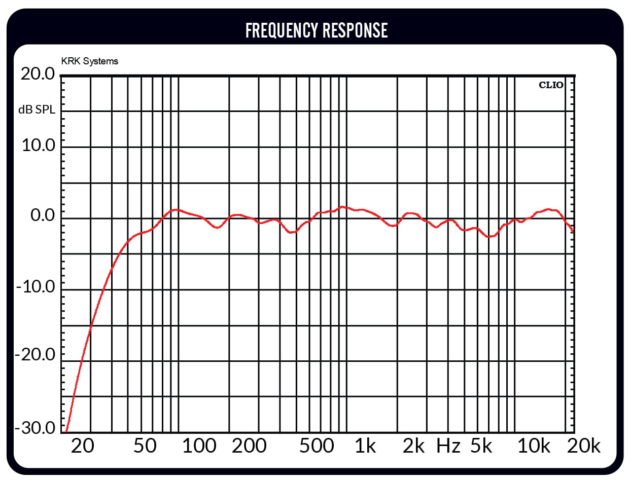
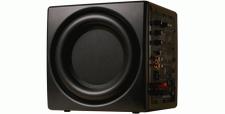
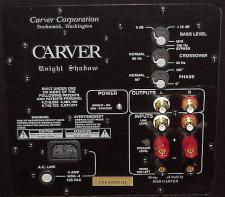 What Bob Carver, the extremely innovative and equally controversial inventor of the Carver True Subwoofer – an 11 inch cube that made deep bass by radically departing from the conventional woofer paradigm – did was exactly that: He designed a subwoofer system that, by a combination of both electronic and mechanical filtration, reduced all frequencies above its intended maximum operating range ( 80Hz – 120Hz), and then boosted his drivers (two very special 7 inch units) to the point where they were able to pump out what had been thought to be impossibly deep bass (20Hz or lower) at, also thought to be impossible, volume levels of 108 to 110 dB.
Something similar was done by Acoustic Research in the “acoustic suspension” speakers first designed and patented by Edgar Villchur. Those effectively raised the bass output by lowering the response at all other frequencies and, with an overall sensitivity in the range of (if I remember correctly) only around 82dB (1W/1meter) they were the first small speaker to be able to get down into the 30 Hz range.
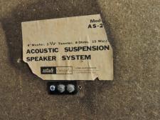 While the AR’s used, other than their usually more compliant suspension, mostly conventional and conventionally-sized woofers and put most of their innovation into their patented approach to enclosure and overall system design, Carver did something entirely different: Claiming in his patent application that conventional (“prior art”) woofers, in order to move large volumes of air, often range from 10″ to 13″ or more in diameter and have a “peak-to-peak stroke” (total forward and back travel, also called “throw”) of 0.6″ to 0.8″, he set out to do something better:
A quick calculation of the amount of air moved per each full stroke in one direction by a conventional 13″ driver using the (admittedly over-simplified) formula of V= AS, where V is the total volume of air moved; A is the gross area of the driver; and S [for “stroke”] is the total peak-to-peak travel of the diaphragm (from fully in to fully out], shows that the total volume of air moved is 106.18 cubic inches. (13″diameter÷2 equals 6.5″ radius. 6.5″ x 6.5″ = 42.25 square inches [r2]. 42.25 square inches x 3.14159 [pi] = 132.73 cubic inches. Finally, 132.73 cubic inches x 0.8 [the larger amount specified for cone travel] = 106.18 cubic inches of total. air movement volume).
The special driver that Carver designed for use in his “True Subwoofer” (also simply called “the Carver Cube”) was just 7 inches in diameter, but had a throw of 2 ½ inches (!!) and two of them – the complement of drivers that Carver chose to use in his 11″ x11″ x11″ subwoofer, moved what he said to be “…just under 200 cubic inches of air. I checked that, using the same technique for calculation as above, and got a result of 192 cubic inches (7”÷2 =3.5″. 3.5″ x 3.5″ = 12.25 square inches. 12.25″ x 3.14159 = 38.48 square inches. 38.48 square inches x 2.5″ total Throw = 96.21 cubic inches x 2 drivers used = 192.42 cubic inches) ― close enough to 200, and hugely impressive.
 But how could he get that much cone throw? Wouldn’t it require huge amounts of power to drive and control it? Yup. That’s why Bob Carver designed not only the drivers, but also self-contained, very special electronics to drive and control them: The True Subwoofer included, among other electronic niceties, two (Class D or very similar, but not called such) amplifier sections of more than 1,000 Watts each (He says that the system delivers more than 2,000 Watts total) to move the woofer diaphragms and a built-in accelerometer setup and corrective feedback circuitry to control their motion and reduce distortion by either undershoot or overshoot.
All of that makes perfectly good sense: Putting two VERY long-throw woofers in any small box (The Carver’s had an internal volume of only 0.495 cubic feet) could make for possible very large variations in internal air pressure, which should logically call for huge amounts of power to overcome. In fact, the filed and approved patent documents do, more than once, specifically refer to pressure build-ups inside the cabinet and state that [the “Power Supply” – meaning the amplifiers and related electronics] “allows the cabinet to be extremely small because large amounts of power can be provided to the drivers to overcome the pressure created by small cabinet volumes”. The documents also state that: “Further, because the pressure created by small cabinet volume can be overcome, it is possible to use drivers with much longer strokes than used in the prior art.”
The fact, though, is that the way the drivers are mounted and driven, they move in a “Push-Pull” manner, with one driver moving “in” as the other moves “out”, and vice versa. The result of this is that the cabinet internal volume remains constant at all times and there’s NO internal pressure build-up. It also means that, with two identical drivers set up the way they are, we have opposite pressures at the front and the back of the box; we’re back to that same old issue of front wave/back wave cancellation; and the issue comes up of why they work at all.
That, plus some even stranger things in the patent documents are what I’ll write about next time.
See you then.